
PowerPlus™ Power Supplies for ESPs
NWL is the leading manufacturer of high voltage/high frequency switch mode technology power supplies for use in powering electrostatic precipitators (ESPs). PowerPlus™ units integrate the controller, the current limiting element and the T/R set functions into one compact high voltage power supply for use on the ESP.
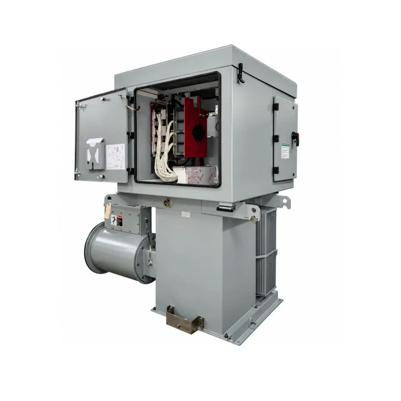
Overview
PowerPlus™ Models
NWL offers the following PowerPlus™ models shown by kV rating:
- 70kV – used with 300mm plate spacing
- 83kV – used with 400mm plate spacing
- 100kV – used with 500mm plate spacing
PowerPlus Design
Carrying on the tradition of supplying the most advanced power supplies for electrostatic precipitators, NWL began design and manufacturing of the PowerPlus™ in 2000. The use of Insulated Gate Bipolar Transistors (IGBT) provides for a power supply design that operates at a much higher frequency when compared to the operating frequency of a conventional single phase unit.
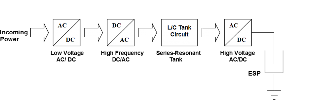
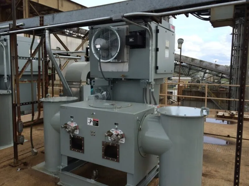
NWL’s unique integrated design, places the power supply and control system on a common assembly. The system is packaged in a NEMA 4 (IP56) rated design for outdoor installations. NWL also has a complete line of mechanical switch designs to facilitate retrofit or new installations. NWL’s PowerPlus™ is configured utilizing the following functional blocks:
Features
The PowerPlus™ Design Process – Built on Proven Technologies, With Enhanced Ruggedness and Better Cooling
In 2000 when NWL entered the switch mode power supply market, there was a design decision to be made – make the smallest and lightest power supply solution or design a unit that is positioned to deal with arcing loads installed in often hot and dirty locations. NWL’s design team chose the latter and as a result came to market with a switch mode power supply (PowerPlus™) that provides:
- A series resonant topology and control mode that turns the power supply into a current source that does not rely solely on the electronics acting quickly to limit the current, but, that the circuit itself, under shorted conditions, is inherently current limiting.
- A cooling system that does not require air filters and minimizes plant maintenance. The heat sink fin spacing is such that the IGBT cooling is not degraded as dust and dirt cannot accumulate and “clog” the fins; no air enters the control box, it is completely sealed.
- A power supply that is manufactured using proven methods previously used in conventional T/R sets. The result a unit that provides the lowest total cost of ownership and integrates with existing infrastructure.
During the first several years of production, NWL put this new switch mode technology into the industries’ toughest environments. NWL then worked with users to continuously to improve the reliability of the product to obtain the high level of reliability that exists on the product being shipped today.
Today’s NWL PowerPlus™ unit has a design that more closely resembles a conventional transformer rectifier than the other switch mode units in the market. The rugged design approach detailed in the three points above has been field validated as the necessary formula for a power supply that is rugged and reliable in the environment of an ESP roof top.
Benefits
The NWL PowerPlus™ has been installed on precipitators in many different industries and applications throughout the world. This product has proven to provide the following benefits to its users:
- Increased collection efficiency
- Decreased kVA for the same amount of power applied to the field
- Faster spark response with less wasted spark current
- Higher Reliability
- Significantly higher power factor when compared to a conventional TR
- Lower initial installation cost
- Reduced space requirement with integrated design
- Able to facilitate buss and guard or cable for HV connection
Specifications
PowerPlus Ratings Table
| Country-Voltage | KV | Individual MA Unit Models | Temperature | Certifications |
| 380 | 83 | 675 / 1110 / 1540 / 1930 | 40°C | Contact NWL |
| 380 | 100 | 920 / 1280/ 1600 | 40°C | Contact NWL |
| 400 | 70 | 400 / 645 / 800 / 1200 / 1370 / 1830 / 2285 / 2860 | 40°C | Contact NWL |
| 400 | 83 | 335 / 540 / 675 / 1010 / 1155 / 1540 / 1930 / 2410 | 40°C | Contact NWL |
| 400 | 100 | 840 / 960 / 1280 / 1600 / 2000 | 40°C | Contact NWL |
| 415 | 70 | 1430 / 1975 / 2460 | 50°C | Contact NWL |
| 415 | 83 | 1205 / 1665 / 2075 | 50°C | Contact NWL |
| 480 | 70 | 400 / 500 / 800 / 1000 / 1500 / 1715 / 2285 / 2860 | 40°C | Contact NWL |
| 480 | 83 | 335 / 420 / 675 / 840 / 1265 / 1445 / 1930 / 2410 | 40°C | Contact NWL |
| 480 | 100 | 1050 / 1200 / 1600 / 2000 | 40°C | Contact NWL |
| 400-480 | 70 | 60 / 120 / 245 / 300 | 40°C | Contact NWL |
| 400-480 | 83 | 50 / 100 / 205 / 255 | 40°C | Contact NWL |
PowerPlusTM General Specifications — All Models
INTERNATIONAL CERTIFICATIONS – For Applicable Models
| Power Supply Standards | Contact NWL |
| Optional CE Certification Includes | EMC Directive (2004/108/CE), Machinery Directive (2006/42/EC), EN 61000-6-4, EN 55011, EN 61000-6-2, EN 60204-1, EN ISO 12100-1, IEC 61000-4-2, IEC 61000-4-3, IEC 61000-4-4, IEC 61000-4-5, IEC 61000-4-6 , IEC 60204-1 |
| Enclosure Environmental Rating | IP56, NEMA4 |
OTHER ELECTRICAL SPECIFICATIONS
| Circuit Breaker IAC Rating @ 480VAC (UL & IEC rated) | 25K |
| Power Factor | 0.94 |
| % Ripple – KVp-p | 3-5 |
| Resonant Frequency – KHz | 50 |
| Arc Shutdown Time – μsec | 30 |
OPERATING CONDITIONS
| Minimum Ambient Temperature | -20 °C |
| Maximum Avg. Ambient Temperature (24 hr) | 40 °C |
| Maximum Ambient Temperature | 50 °C (for up to 4 hours) |
| Maximum Oil Temperature Rise | 40 °C |
| Maximum Tank Surface Temperature | 75 °C |
| Maximum Relative Humidity | 100% |
| Maximum Permissible Altitude | 1000 m (3300 ft) |
EXTERIOR SPECIFICATIONS
| Nameplate Material | Aluminum 0.32” (8 mm) thick, satin finish |
| Paint (primer) | High solid alkyd primer, VOC compliant, gray, 1-1.5 mils (25-40μm) |
| Paint (top coat) | High build acrylic enamel, semi-gloss, 1-1.5 mils (25-40μ) |
| Paint (color) | ASA 61 gray (RAL 7042) |
CONNECTIONS
| Oil Level Switch Ratings | 20VA contacts |
| Minimum Ground Wire size | #2 AWG Cu. per NEC, section 250 (35 mm2 Cu.) |
| Input Connection | Stabs for 5/16” – 3/8” ring lugs (8-10 mm), 1⁄2” ring lugs for 120 kW/100 kV units |
| Output Termination | 1⁄2” NPT Female on HV bushing |
| External Safety Ground Termination | 3⁄83⁄8-16 UNCF, (9.5 mm) |
| Internal Neutral Ground Termination | 3⁄8-16 x 1” stud, (10 mm) |
| Low Voltage feed thru | 1⁄4-20 UNCF epoxy feed thru, (7 mm) |
OTHER
| Windings Conductor Material | Copper wire |
| Insulation Class | A |
| Dielectric type | Cross Grade 206 Mineral Oil (or equivalent) or Dow Corning 561 Silicone Fluid |
Paint Specifications
There are three finish options for PowerPlus™ – one acrylic enamel paint and two powder coating finishes . The standard paint finish is VOC compliant, high-build acrylic enamel, suitable for most ambient conditions, that includes primer, top coat and color coat:·
- Paint Primer: High solid alkyd primer, VOC compliant, gray, 1-1.5 mils (25-40μm)
- Paint Top Coat: High build acrylic enamel, semi-gloss, 1-1.5 mils (25-40μ)
- Paint Color: ASA 61 gray (RAL 7042)
See detailed paint specifications (PDF) for more information about acrylic enamel finishes.
For more challenging environmental conditions such as exposure to salt water and offshore installations, NWL also offers a powder coat rated for extreme corrosion resistance. View info on NWL Optional Powder Coat System (PDF).
Grounding Specifications
With over 1200 PowerPlus™ units in service, NWL has learned a many ‘best practices’ with respect to installation, operation, and maintenance. A very important feature to greatly ensure trouble-free operation is to follow the grounding procedures as shown in the PowerPlus™ manual. The following three grounding paths must be in place to ensure proper operation:
- Electrostatic Precipitator (ESP) Grounding: The precipitator collecting plates must be securely grounded to the frame of the ESP box. All sections of the box itself must be tied to the plant ground grid. This must be the same ground grid used for the incoming PowerPlus power source. It has been NWL’s experience that if the power source ground grid is not the same as the ESP ground grid, IGBT failures may occur during sparking or arcing conditions.
- Low Impedance Return Path: Since the output current of the PowerPlus™ unit is much greater than a conventional T/R set (50 kHz to 120 Hz), it is important to have a low impedance path (at 50kHz) from the collecting plates (inside the ESP box) to the PowerPlus™ HV tank ground. To get this low impedance, the HV ductwork should be kept as short as possible, and all flange connections must be jumpered with at least two pieces of copper braid to guarantee a good connection through the joints. Because this is such a critical area, a redundant path is required using #6 AWG copper (minimum). This copper wire must be solidly grounded where the HV ductwork enters the ESP. The wire must then run alongside the ductwork (also known as pipe and guard) and terminated at the ground boss located directly on the HV tank. It has been NWL’s experience that not installing this ground return wire may cause premature failure of the IGBT’s under sparking or arcing conditions within the ESP.
- PowerPlus Grounding: Many ESP boxes have a heavy copper wire (» 1/0 AWG or larger) that runs around the perimeter of the ESP roof, drops down along the side, and ties to the plant ground grid underneath the ESP. To minimize problems due to voltage and arcing transients, it is advisable to securely tie the frame of each PowerPlus unit to this heavy ground wire that runs around the perimeter of the ESP. Each unit should be tied to this ground using a cable sufficiently sized per NEC. The ground wiring must not be “daisy-chained” from one unit to the next unit. Each unit must be individually routed to this ground.
It is strongly recommended that any installed PowerPlus units be checked to make sure they are properly grounded as shown in this drawing (PDF). It may avoid premature problems with the units. Failures caused by improper grounding may affect the NWL original equipment warranty as stated in the PowerPlus™ manual.
Resources
Spec Sheets
Drawings
Case Studies
Application Notes
Certifications
NWL is an AS9100:2016 and ISO 9001:2015 certified manufacturer of transformers and power supplies for industrial applications and also provides a CE Declaration of Conformity for its PowerPlus switch mode power supply (SMPS).
Related services
Related services
NWL provides service and support for electrostatic precipitators (ESP), power supplies, transformers and inductors.
If the NWL equipment was supplied or acquired as part of a system from another firm, please contact that company for any service needs. If they are unable to satisfy the service requirements, then contact NWL
Startup and Commissioning
NWL’s expertise goes well beyond the production phase. Our fully trained personnel are ready to help you get your new equipment connected, properly set up, and running efficiently. Our service technicians and engineers have traveled across the globe, working with customers from various backgrounds and experiencing every possible environment.
Maintenance and Repair
NWL products are available for purchase as spare or replacement parts. We offer tailor-made maintenance packages to ensure that the equipment operates efficiently, which includes yearly inspections, preventive maintenance and repair services from our technical and engineering experts. Additionally, upgrade or retrofit options to address part obsolescence, enhance system performance, design, and software, and support long-term cost savings are available to all our customers.
On-Call and Onsite Assistance
For on-call and onsite assistance, NWL’s dedicated team is there to take your call. We work around the clock, ensuring that you have the help you need whenever you need it. NWL offers global, remote support anytime, regardless of your time zone.
Custom Engineering Solutions
We offer customized engineered products and services to meet your reliability requirements. It starts with a good understanding of the product need and the application environment and solid collaboration between the parties involved.