Transformer/Rectifier Sets Design Specifications
Equipment provided by manufacturer shall be of a heavy duty industrial grade design, suitable for use in a power plant operating environment.
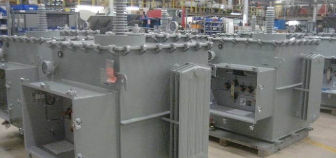
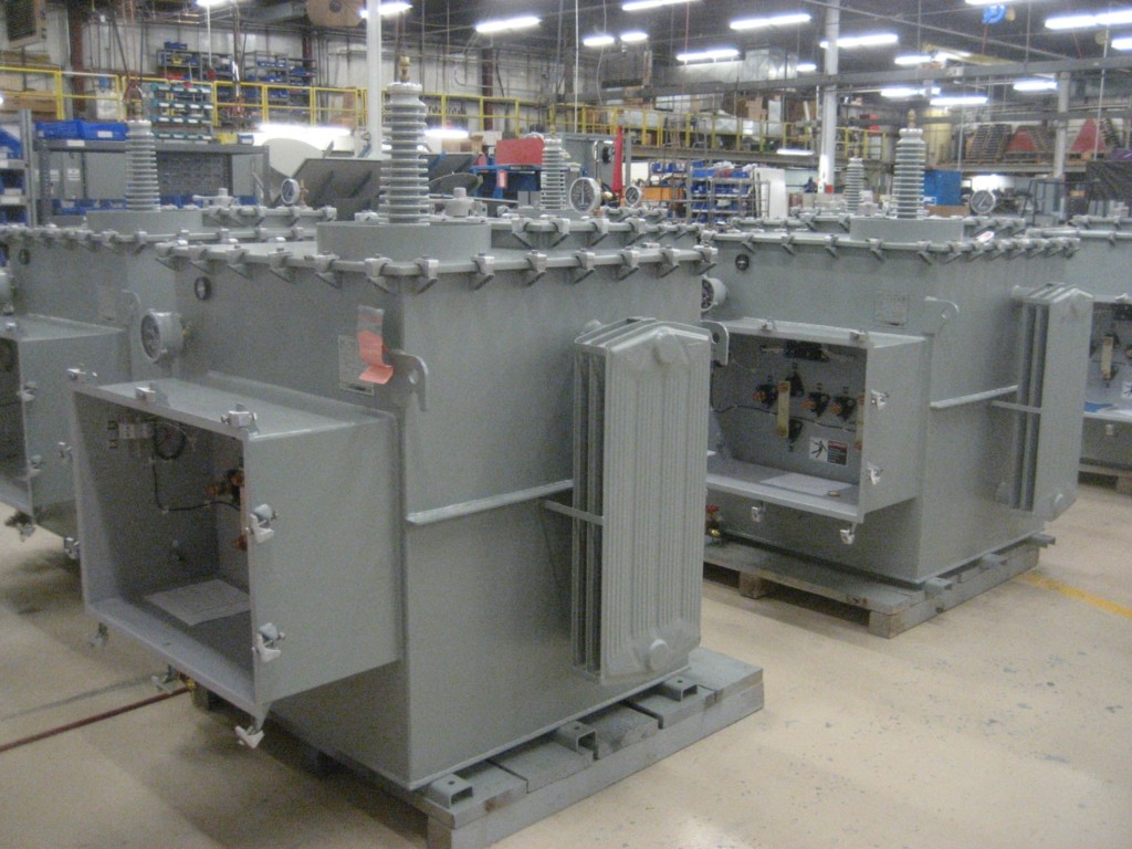
The transformer-rectifier set shall conform to the best modern practice in design and construction. Rectifiers, air core reactors and voltage dividers shall be mounted on a single removable module to minimize transportation damage and allow for rapid servicing of equipment.
The transformer rectifier set shall be fluid immersed type OA suitable for outdoor installation, exposed to elements in various climates and elevations (see operation conditions for details). Insulating fluid must be certified to contain less than 2 PPM of PCB. The tank shall be designed to minimize the volume of the insulating fluid.
Switch Options
- Each transformer-rectifier can be equipped with an internal disconnect ground switch.
- Each transformer-rectifier can be equipped with and external ground switch. The ground switch shall be equipped with a polycarbonate inspection window for visual verification of ground.
- Each transformer rectifier can be equipped with an external disconnect ground switch. The switch will be designed to ground the precipitator and isolate the transformer rectifier from the precipitator load. The switch shall be equipped with a polycarbonate inspection window for visual verification of ground.
- Each transformer-rectifier can be equipped with an external disconnect splitter switch. The switch design will allow the use of a single bushing transformer rectifier to power two independent bus sections. The switch shall provide the following modes of operation.
| Position |
Bus A |
Bus B |
| 1 |
Fullwave |
Fullwave |
| 2 |
Fullwave |
Ground |
| 3 |
Ground |
Fullwave |
| 4 |
Ground |
Ground |
The switch shall be equipped with a polycarbonate inspection window for visual verification of switch position.
- Each transformer-rectifier can be equipped with no switch if desired.
Switches are to be designed for use as an off load DC circuit switching mechanism and are not to be used in place of safety grounding for personnel safety. All switches shall have provisions for mounting customer supplied interlocks (Kirk, Superior, Castell, etc. See drawing A105811 for specific approved interlocks). Interlocks should have a bolt extension of 0” (0mm) to ¼” (6.4mm).
Operation Conditions:
The transformer rectifier set shall perform in a satisfactory manner at geographic locations not in excess of 3,300 feet (1000 meters) above sea level for ambient temperatures not exceeding 40°C (104 °F). Increased altitude and ambient temperature (to 50°C) are available as options to the standard design.
The transformer rectifier sets can be located outdoors exposed to dust, salt, and extreme weather conditions. The range of weather conditions will be from -40° F to + 104° F dry bulb temperature and 10% to 100% outdoor relative humidity. The sets can be exposed to direct sun in summer climates with rain conditions existing intermittently, and snowfall during the winter season.
Design and Construction Features:
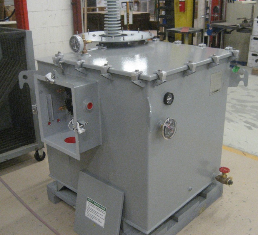
The tank shall be constructed using 10 gauge steel (minimum) with welded joints and stiffeners where required. The tank shall be completely sealed and in compliance with NEMA 4 construction. Clamped and reusable gasketed top cover shall be oiltight and weatherproof, and arranged so that it can be lifted for inspection with a minimum of effort. This cover provides access for servicing major components of the T/R set. All tanks shall be 100 % leak tested with a dye penetrate leak test system. All tanks shall be pressure tested to 4 PSIG upon final inspection, and shipped with 1 PSIG nitrogen purged head space (above oil).
Lifting Provisions:
The tank shall be equipped with lifting lugs installed above the center of gravity of the tank and of sufficient strength to lift the tank complete (full of insulating liquid and all internal components).
Low Voltage Junction Box:
All low voltage electrical connections to the T/R set (power, control, and instrumentation) shall terminate in a NEMA 4 (IP 54) rated junction box. A NEMA 3R rating will be used when the current limiting reactor is located in the low voltage junction box (not available on some units) to provide adequate ventilation/cooling. The latter is done to save feeder wiring.
Finish:
The finish shall consist of an iron phosphate pretreatment over pickled and oiled steel followed by 1 to 1.5 mils dry film thickness (DFT) of a high solid alkyd primer and 1 to 1.5 mils DFT of high build acrylic enamel. The total film thickness is 2 – 3 mils DFT. Standard paint color is ASA 61 gray. An epoxy paint system is available for extreme environmental conditions as an option.
Rectifier Assemblies:
The silicone rectifier assemblies shall be a positive locking plug connected module type, such that they are easily removable. The rectifier assemblies shall be rated at a minimum of 180 KVPIV per leg (220 KVPIV per leg for 110 KVpk Units) and utilize controlled avalanche diodes.
Current Limiting Reactor:
The seller can supply a suitable sized current limiting reactor located outside the T/R tank to minimize heat duty on tank and fluid. Optional taps can be provided. The maximum impedance of a current limiting reactor located in the low voltage junction box will vary with the ratings of the T/R set. Larger current limiting reactors may need to be located in a separate, NEMA rated, standalone enclosure.
Grounding Terminal:
The tank shall be equipped with a two type 304 Stainless Steel ground pads located on opposite sides, diagonal corners, near the bottom of the tank. Each ground pad has two ½ – 13 UNC threaded holes with protective plugs. The pads are for electrical grounding of the T/R set and will serve as the positive connection between the precipitator and the set. The ground pad shall not be painted with primer or any other insulating type materials.
Radiators:
Radiators, when required, shall be designed to resist damage during hoisting and installation. Purchaser will provide lifting spreader-bars to provide normal protection during installation. Preference will be given to minimize the number of radiators due to their extreme vulnerability.
Nameplates:
A corrosion resistant aluminum nameplate shall be permanently affixed to the tank in a conspicuous location. The following data sheet shall be included on the nameplate by the Seller:
- Manufacturers Name, Address and Phone Number
- Model Number
- Serial Number
- Manufacturing Date
- KVA Rating
- Input Voltage
- Input Current
- Current Form Factor
- Output Voltage (KV peak, no load)
- Output Current (mADC)
- Number of Phases
- Input Frequency
- Cooling Class (per ANSI C57)
- Maximum Ambient Temperature
- Maximum Temperature Rise
- Weight (lbs., Kgs.)
- Volume of Oil (gals., liters)
- Type of insulating fluid
- Schematic Diagram
High Voltage Bushing:
The high voltage bushing shall be cover-mounted, semi-outdoor type, removable without de-tanking (except side mounted bushings), and shall have connections for the high voltage buses. The bushings shall be wet process porcelain, and shall be oil-tight. Fluid filled bushings should contain dielectric fluid compatible with the major dielectric fluid system. The bushing cover shall be provided with bus duct flanges. The bushing cover shall be equipped with a steel drain tube for moisture removal.
Drain Valve, Filling Hole and Vent:
The tank shall be equipped with a 1” NPT drain valve, with plug and sampling device, to allow drainage of tank. A 1” NPT fill coupling shall also be provided in the tank top. A pressure relief valve and a nitrogen access valve shall be installed in the fill coupling.
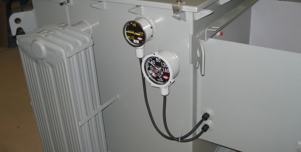
Liquid Level Indicator:
A liquid level indicator shall be provided to give visible indication of the liquid level. The gauge shall be indelibly marked to show the approximate liquid level at 25°C (77°F). Alarm contacts can be provided as an option.
Temperature Indicator:
The tank shall be equipped with a dial-type thermometer to indicate liquid temperature. NO/NC alarm contacts are provided as standard for remote indication. Alarm contacts are brought back to the terminal blocks, located in the low voltage junction box. Temperature indicator shall monitor near top oil temperature, NOT tank wall temperature. An independent well shall be provided to allow gauge replacement without requiring fluid removal. Dual NO/NC contacts are available as an option.
Surge Arrestor:
A surge arrestor shall be provided for all instrument feedback signals. Surge arrestors shall be physically located inside the low voltage junction box. Metering resistors shall be adjustable with Seller established settings within NWL’s standard selection range.
Metering Resistors:
An 80 megohm high voltage divider resistor network (120 megohm for 110 KVpk units) will be located within the T/R tank, immersed in dielectric fluid. A milliamp shunt resistor and/or a kilovolt meter multiplier resistor shall be provided (when specified in the options selection) and located inside the low voltage junction box.
Air Core Reactor:
An air core reactor shall be provided to protect the rectifiers from damage due to high frequency current surges, which may occur in the ESP operation.
Transformer Rectifier Set Characteristics:
The transformer shall be a two-winding, single phase power rectifier type. The high voltage windings shall be insulated for 1.5 timers rated voltage. The low voltage windings shall be insulated for 2.5 KV Hipot tests. The standard temperature rise for the unit shall be 55°C above 40°C ambient. An optional 45 °C rise above a 50 °C ambient is also available.
Insulating Fluid:
T/R sets shall be shipped with a full charge of new mineral oil insulating fluid. Silicone fluid is also available as an option. Typical fluid properties, along with the ASTM test methodology, can be supplied upon request.
Tests:
The following tests will be made on all T/R sets:
- Resistance measurements of all windings.
- Ratio tests on the rated-voltage connections.
- No-load loss at rated primary voltage on the first set of each new design.
- Exciting current at rated voltage.
- Short circuit losses at rated primary current on the first set of each new design.
- Applied potential test of 2.5 KV between low voltage winding and ground for one (1) minute.
- Induced potential test of 1.5 times rated voltage for 18,000 cycles on transformer portion of power supply.
- With rectifiers connected, surge test of transformer shall be arced to ground five (5) consecutive times from each high voltage terminal at rated frequency and 100% of maximum rated voltage.
- The complete rectifier assembly shall be given a thorough connection check. Then, 120% of the transformer rated voltage shall be applied to the power supply open circuited for five (5) minutes.
Test will be performed with certified, calibrated test equipment with calibration methodology traceable to a nationally recognized code/standards organization.